Behind every industrial plant that operates safely, efficiently, and in compliance with regulations lies an element that is often underestimated but absolutely essential: the electrical diagram. It is not merely a technical drawing, but the actual logical blueprint of a plant—the document that defines how each component is connected, how it interacts with others, and how it should be maintained, modified, or expanded over time.
The design of industrial electrical schematics is a discipline that requires a wide range of skills: in-depth knowledge of relevant technical standards, proficiency in specialized software tools, an understanding of process logic, and the ability to translate complex operational requirements into clear, unambiguous representations that can be used by any qualified technician. A well-designed electrical schematic is the difference between a system that can be managed independently and one that relies constantly on the original designer for every intervention.
In an industrial environment increasingly focused on traceability, human-machine safety, and regulatory compliance, neglecting the quality of technical documentation exposes companies to real risks: non-compliance during inspections, maintenance difficulties, delays in emergency response, and vulnerability in the event of audits or legal disputes. In this article, we analyze the regulatory requirements governing the preparation of electrical schematics, the best practices adopted by industry professionals, and the concrete consequences of non-compliant documentation.
What defines an industrial electrical diagram and why it is a strategic document
An electrical diagram is a graphical and symbolic representation of an electrical system, in which every component, connection, and protective device is described using standardized symbols and unique references. In an industrial context, this documentation is far more complex than that of residential systems because it must manage hundreds or thousands of connection points, automation systems, safety logic, and interfaces with various types of machinery.
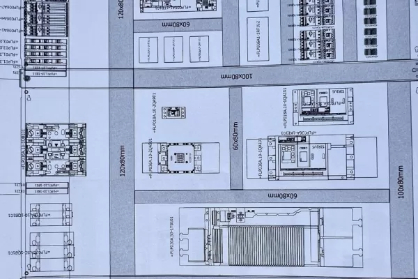
Generally, the electrical documentation for an industrial plant is organized into several complementary levels. The single-line diagram provides an overview of the system, showing the distribution of power from the supply points to the main loads. Functional and topographical diagrams, on the other hand, go into detail regarding individual circuits, connections between devices, and the physical layout of components within the control panel. These are supplemented by cable lists, terminal block diagrams, parts lists, and documentation related to automation and safety systems.
The strategic value of these documents extends far beyond the design phase. A well-drafted electrical schematic is the tool used to perform maintenance, diagnose faults, plan expansions, and demonstrate compliance during inspections. In other words, it is the technical asset that accompanies a system throughout its entire lifecycle and determines its effective manageability over time.

Regulatory requirements: the rules that guide design
The design of industrial electrical schematics is governed by a comprehensive regulatory framework that defines symbols, graphical conventions, safety criteria, and documentation requirements. Familiarity with these standards is not optional but a prerequisite for creating compliant and safe systems.
The primary reference standard is CEI EN 60204-1, which establishes the requirements for the electrical equipment of machines, including the technical documentation that must accompany every system. This is complemented by CEI EN 61082, which is specifically dedicated to the preparation of documents used in electrical engineering and defines the rules for drafting diagrams, tables, and lists. As for graphic symbols, the reference is IEC 60617, an international standard that ensures the comprehensibility of diagrams regardless of language or country of origin.
At the system level, CEI EN 61439 governs the design of low-voltage switchgear, establishing specific requirements for the accompanying documentation. For aspects related to human-machine safety, the standards of the ISO 13849 and IEC 62061 series also apply, requiring specific documentation for the safety functions implemented in the system.
Compliance with these standards is not limited to the initial design phase. Every modification, update, or maintenance intervention must be recorded in the documentation, ensuring that the link between the as-built design and the actual status of the system is kept constantly up to date.
Best practices and consequences of non-compliance
A good designer knows that an electrical schematic is not judged solely on its technical accuracy, but also on its clarity, consistency, and usability. Among the established best practices in the industry, the use of dedicated CAD software such as Eplan is now a well-established standard: these tools allow for the automated generation of schematics, cable lists, terminal blocks, and parts lists, drastically reducing the risk of errors and ensuring full consistency across different documents.
Other fundamental criteria include the unique naming of each component, the hierarchical structuring of circuits, the separation of power and control circuits, and the correct identification of safety functions. The documentation must be designed to be readable and usable by any qualified technician, not just the original designer.
Neglecting these aspects has real-world consequences. Incomplete or outdated documentation can lead to the system being shut down during testing, penalties during inspections, insurmountable difficulties in managing malfunctions, and significant delays in maintenance activities. In the most critical cases, inadequate documentation regarding human-machine safety functions can expose the company to legal liability in the event of accidents, as well as making it difficult to demonstrate compliance with applicable European directives.
Investing in the quality of electrical schematics, therefore, is not an incidental cost of the project: it is an operational, regulatory, and legal safeguard that pays for itself over the entire lifecycle of the plant.
Electrical schematics: the common language between designers, clients, and maintenance technicians
A well-designed electrical diagram is much more than a technical document: it is the shared language that allows designers, installers, maintenance technicians, and regulatory bodies to immediately understand how a system works, what its safety protocols are, and how to intervene at every stage of its lifecycle. The quality of this documentation directly impacts the reliability, safety, and longevity of the entire production system.
Every diagram we create complies with applicable European and American regulations, incorporates the human-machine safety functions specified in the design, and provides the customer with comprehensive, up-to-date documentation that can be immediately utilized by any qualified technician. Because we know that the value of a system is not measured solely on the day of delivery, but by how easily it can be managed, maintained, and upgraded over time.